Thursday, April 26, 2012

Project 2


For Project 2, I based my design off of Jean Nouvel's Arab World Institute facade (pictured above).
It is a shutter system that opens and closes with changing amounts of sunlight. For my project, instead of directly basing it on sunlight, I based it on the time of day to simulate different light conditions.  


(pictured above) Shutter aperture at 8:00

(pictured above) Shutter aperture at 2:00


(pictured above) detail of panels

To begin, the curtain panels were made. At Professor Wei Yan's suggestion, I followed a tutorial from Buildz to create the panels. The panel consist of triangles snapped along four host points that follow their respective arcs (Fig A & Fig B). Changing the host point changes the aperture of the triangular shutters.


Fig A

Fig B

After creating the curtain panels, I loaded them onto a triangular mass family, simliar to the panels from Project 1. I chose not to use my original model from Project 1, because that project was composed of surfaces and not actually masses. From the triangular mass family, I loaded it into the ProjectParameters file (Fig C).


Fig C

In the ProjectParameters file, I set up a Time of Day parameter, setting it under the Project Information category and setting it to an integer type:


After these steps in Revit, I used C# to link the Time of Day parameter with the host point (refer back to Fig C). The idea is that if the Time of Day parameter changes, the host point also changes and moves the shutters accordingly. The Curtain Panel sample code and parts of the External data code were used to implement this idea.


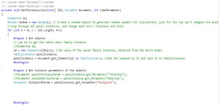
The first step was to change the massID and panel instances to match the IDS in my revit file:


After this, parts of the external data code was used to get the time of day parameter from the revit file:

Then, the host point Parameter was retrieved (last line):

Finally, the host point Parameter was calculated to be the time of day/12.0 and set to its new value:


References:


In addition, a thank you to Professor Wei Yan for his help with this project.


Thursday, March 22, 2012

Project 1

pictured above: rendering from Zaha Hadid


BIM Rendering


interior rendering


The first step I used in making my BIM model was to get the points at the corners of each triangular facet. I used an imported sketchup model to lift the points to the correct height.


From there I connected these points with reference lines and made surfaces to get the form.


The limitation with this method is that floors cannot be created from the mesh geometry.

I added height parameters to each point, and also a Z Scale Factor to control the overall form better.

Model with individual points moved up.


Mass with Z Scale Factor of 3


Mass with Z Scale Factor of 2


To solve the problem of not being able to create floor plates, I attempted to use contours to create a conceptual mass. However, the problem was that revit could not use all the contours above to create a smooth form.
I had to create contours section by section. In addition, I could not join them, so it defeated the purpose of being able to create floor plates in a project.


Pictured above is my parametric envelope family. The radius can be changed to be thicker. In addition, material parameters were added to the glass and steel.


Finally, I used the subdivide method to divide certain faces of the model, and added my parametric family to the surfaces.


Criticism: I found that using Revit to model a surface such as the Guangzhou Opera House proved to be a bit more difficult than other programs such as Maya or Rhino. In Revit, modeling a mass with many surfaces is not as intuitive as in other programs.